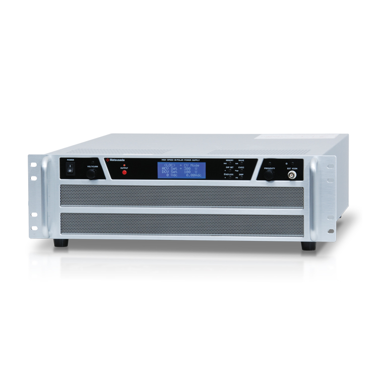
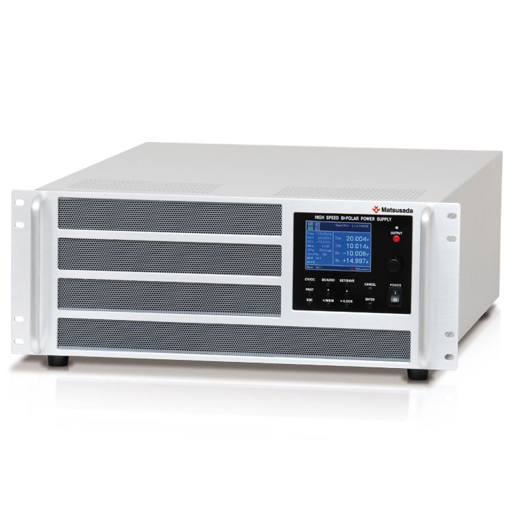
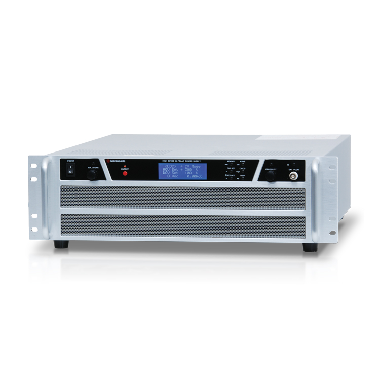
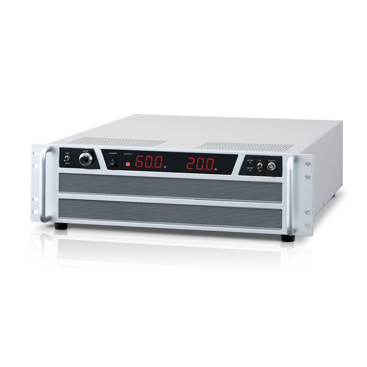
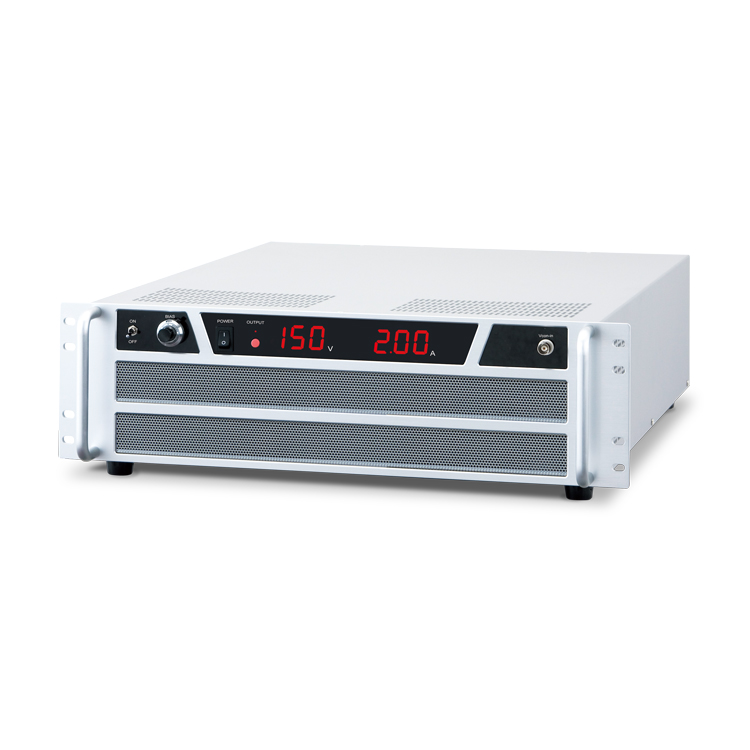
ULTRA HIGH SPEED BIPOLAR POWER SUPPLY
- Voltage range: ±20V to ±60V
- Power: 150W to 2000W
- Frequency bandwidth:
DC to 200kHz - Built-in function generator as standard
Ultra fast response Four-quadrant bipolar power supply built-in function generator
The DOSF series is equipped with a built-in function generator enabling its compact size and ultra-fast response. Any waveform can be programmed easily from the front panel, and it features memory settings and protection functions. With communication options, external control is available. You can use this DOSF series as an ultra-high-speed bipolar amplifier enabling an external signal input.
FEATURES AND BENEFITS
- Ultra-fast response of DC to 200 kHz
- Function generator as standard
- Waveform with less distortion by DDS method (DC to 200 kHz sine wave, square wave, and triangle wave)
- Individual setting of DC/AC output and CV/CC mode, making the unit user-friendly with simple operability (DC to 200 kHz in CV mode and DC to 100 kHz in CC mode for sine wave, square wave, and triangle wave)
- External control with communication options (USB, LAN, RS-232C, RS-485, and GPIB)
- High legibility with LCD display using high contrast white LED backlight
- Waveform generation, sequence operation, and various measurements on a single power supply
- All settings and operations only on the front panel
- Up to 6000W with Master-Slave operation

APPLICATIONS
- Driving capacitive loads (capacitors)
- Biasing inductive loads (coils, transformers, etc.)
- Various motor testing
- Solar inverters (PV inverters)
- Evaluation test for solar panel related devices
Note: We do not design this bipolar power supply for charging and discharging batteries.
For battery charge and discharge application, please refer to the Battery Cycle Tester product page.
Models
* Consult with our sales office about different specifications from the following list.
| Model | Output | ||
|---|---|---|---|
| Voltage | Current | Power | |
| DOSF20-7.5 | ±20 V | ±7.5 A | 150 W |
| DOSF20-15 | ±15 A | 300 W | |
| DOSF20-30 | ±30 A | 600 W | |
| DOSF20-60 | ±60 A | 1200 W | |
| DOSF20-100 | ±100 A | 2000 W | |
| DOSF25-6 | ±25 V | ±6 A | 150 W |
| DOSF25-12 | ±12 A | 300 W | |
| DOSF25-24 | ±24 A | 600 W | |
| DOSF25-48 | ±48 A | 1200 W | |
| DOSF25-80 | ±80 A | 2000 W | |
| DOSF45-3.3 | ±45 V | ±3.3 A | 150 W |
| DOSF45-6.6 | ±6.6 A | 300 W | |
| DOSF45-13.3 | ±13.3 A | 600 W | |
| DOSF45-16 | ±16 A | 720 W | |
| DOSF45-26.7 | ±26.7 A | 1200 W | |
| DOSF45-44.4 | ±44.4 A | 2000 W | |
| DOSF60-2.5 | ±60 V | ±2.5 A | 150 W |
| DOSF60-5 | ±5 A | 300 W | |
| DOSF60-10 | ±10 A | 600 W | |
| DOSF60-20 | ±20 A | 1200 W | |
| DOSF60-33.3 | ±33.3 A | 2000 W | |
Functions
Basic Waveform Generation
DOSF is equipped with a built-in function generator that produces basic waves such as sine, rectangular, and triangle waves.
The frequency range can be set between 1 Hz and 200 kHz. You can adjust amplitude; start phase (for sine wave), on-phase control (for sine wave), and duty ratio (for rectangular/triangle wave).
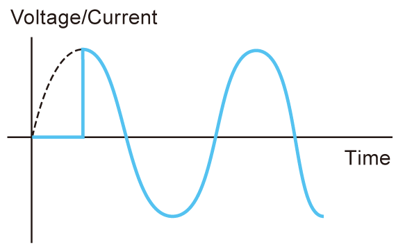
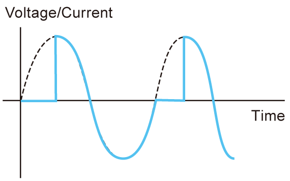
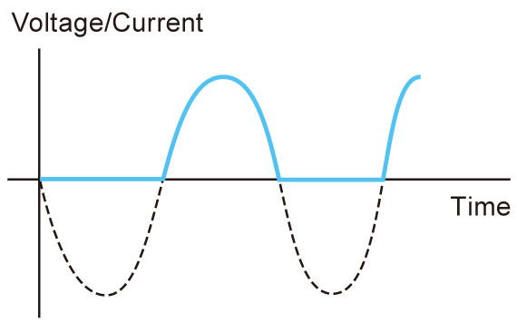
Application
Power activation test, Inrush current measurement, waveform fluctuation test
Sequence Functions
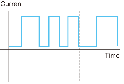
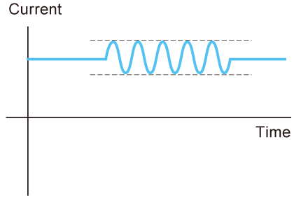
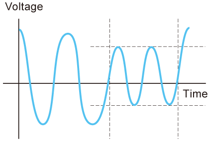
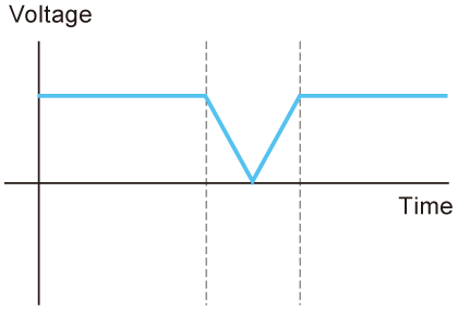
The DOSF series is equipped with programmable sequence functions such as step time, step amplitude ramp, CV/CC mode, frequency sweep, AC superposition, step jump, and jump times. These useful functions help to program the desired waves in very flexible manner, enabling to support laboratory and research works efficiently.
If amplifier’s output turns off while it is running a sequence program halfway through, the leftover sequence will not run but it is re-activated from the beginning of the original sequence.
- Step time: 10 ms to 1999 s 999 ms (resolution: 1 ms), ramp and AC waveform is 50 ms
- Up to 16 steps per program and settings for 3 programs can be saved.
- Can be set CV/CC mode per program
- Frequency: Infinite, 1 to 999
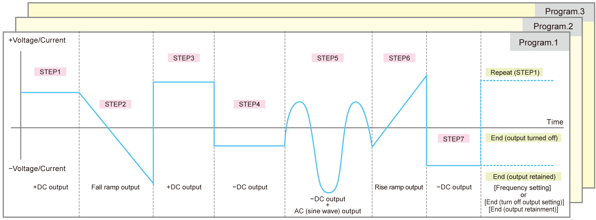
Sequence functions help to create complicated waves like below to be simply and easily edited.
Applications
Testing of motors, Pulse power supply and Various evaluation
Measurement Functions
The DOSF series is equipped with programmable sequence functions such as step length, step amplitude ramp, CV/CC mode, frequency sweep, AC superposition, step jump, and jump times. These useful functions help to program the desired waves in a very flexible manner, enabling to support laboratory and research works efficiently.
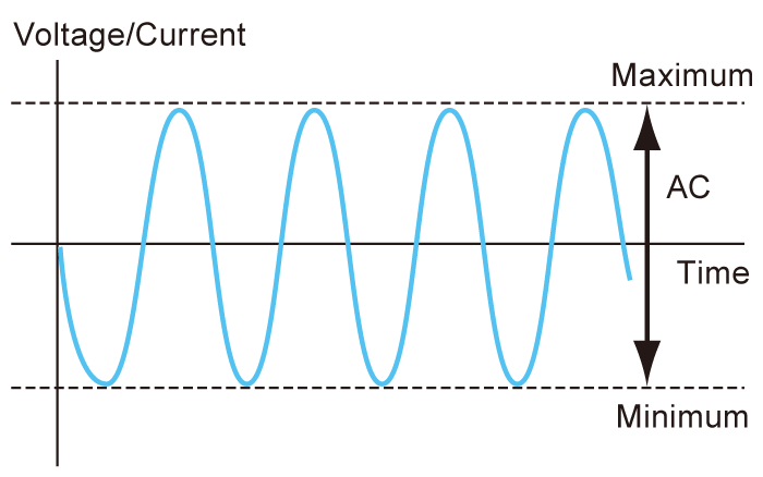
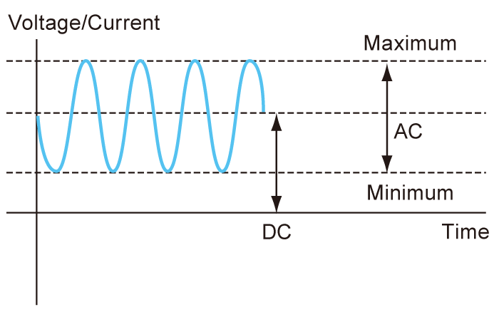
Memory Functions
During fundamental wave operation, output voltage (in CV mode), output current (in CC mode), CV/CC setting, and waveform setting can be saved in 10 set-up memories.
As sequence programs can be saved in up to three, it is useful when using frequently used multiple waveforms or sequence operations.
- Other functions:
- DOSF is equipped with Protection function, Key-lock function, and CV/CC switching, as standard options.
Specifications
Options
* Selecting each individual option simultaneous in -LUs1, -LEt, and -LGob is not allowed.
- -LD
-
Interlock
- -LEt
-
LAN interface port *
Enable digital control via LAN[Control items]
Output ON/OFF, Voltage/Current setting (AC and DC), Switch of constant voltage/constant current, Frequency setting, Waveform setting (sine wave, square wave, and triangle wave), Phase setting (sine wave), Duty setting (square wave and triangle wave)
- -LF
-
Floating ground (withstanding voltage of 200 Vdc)
The negative terminal of the output can be floatable up to 200 V. However, please take note that the external control signal source (such as a function wave generator) and the common measuring device that connects to the amplifier's monitor terminal will also become floating potential in this case.
- -LGob
-
Optical interface port *
This option changes the standard interfaces to a built-in optical interface port. By combining this option with an adapter for optical connection (sold separately), communication between the control device and the power supply can be controlled in an isolated state. Be sure to select this option when using the product in the following environments.- -LGob: Optical interface port + optical cable 2 meters
- -LGob(Fc5): Optical interface port + optical cable 5 meters
- -LGob(Fc10): Optical interface port + optical cable 10 meters
- -LGob(Fc20): Optical interface port + optical cable 20 meters
- -LGob(Fc40): Optical interface port + optical cable 40 meters
Select the optional optical interface port (-LGob) when using the bipolar power supply under the following conditions.
- Noisy environments such as factories (example: when motors or coils are used near loads or power sources).
- If this power supply and your controller (PC or PLC) cannot be installed within 2 meters.
- When there is a possibility of arcing or output short-circuit.
[Control items]
Output ON/OFF, Voltage/Current setting (AC and DC), Switch of constant voltage/constant current, Frequency setting, Waveform setting (sine wave, square wave, and triangle wave), Phase setting (sine wave), Duty setting (square wave and triangle wave)
- -LMsm: Master machine for master-slave control
-LMss: Slave machine for master-slave control -
By connecting a master machine and a slave machine with dedicated control lines, the master machine can control all slave machines at once. Parallel connection can increase the current that is insufficient for a single operation. Up to three units in total can be connected: one master unit and up to two slave units.
Note: Precautions for using the master-slave operation- Only master-slave connection is available for the same model.
- In parallel operation, the frequency range is narrower.
- It can also operate on a single.
- Factory adjustment is required when changing the master-slave combination.
- Either communication option (-LEt、-LGob, or -LUs1) is necessary for only the master unit when the power supplies in the master-slave connection are controlled by digital communication. However, if you want to perform digital communication control on the slave unit alone, these options are also required for the slave unit.
- -LS
-
External output ON/OFF (Output ON/OFF)
- -LUs1
-
USB interface port *
Enable digital control via USBControl items
Output ON/OFF, Voltage/Current setting (AC and DC), Switch of Constant Voltage/Constant Current, Frequency setting, Waveform setting (sine wave, square wave, and triangle wave), phase setting (sine wave), Duty setting (square wave and triangle wave)
- -L(220V)
-
Changing the input voltage
200 Vac to 240 Vac ±10% single phase, 50 Hz/60 Hz input (150 W and 300 W models only)
* Selecting each individual option simultaneous in -LUs1, -LEt, and -LGob is not allowed.
How to order
When ordering, add Option No. in the following order by alphabet, and input voltage to Model No.
<Example> DOSF60-20-LDFMsLMsmSUs1, DOSF20-100-LDFGob(FC20)LMssS
Accessory
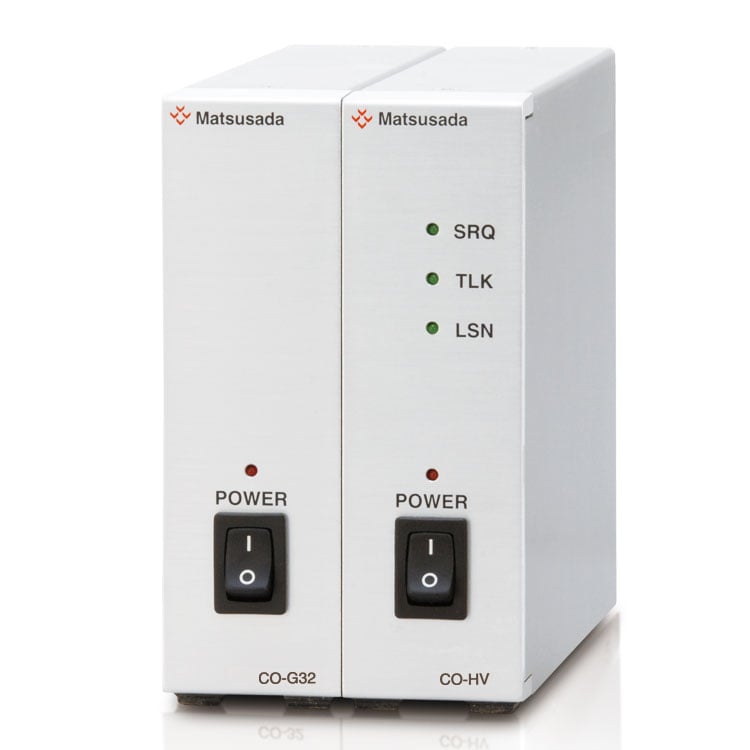
- Interface adapters
-
To use the optical interface, you need to prepare an optical interface adapter separately. The following interface adapters are available according to your controller port.
For details, refer to CO/USB series.- CO-E32: LAN to optical interface adapter
- USB-OPT: USB to optical interface adapter
- CO-OPT2-9: RS-232C (9 pin) to optical interface adapter
- CO-OPT2-25: RS-232C (25 pin) to optical interface adapter
- CO-OPT4-25: RS-485 (25 pin) to optical interface adapter
- CO-G32: GPIB to optical interface adapter (Discontinued in December 2028)
Example of communication with optical fiber 
- AC INPUT CABLE
-
Standard
up to 300 W modelCABLE TYPE2
Power input end
Input plug125V/15A Standard
more than 600 W modelCABLE TYPE5
Power input end
Input plug300V/25A
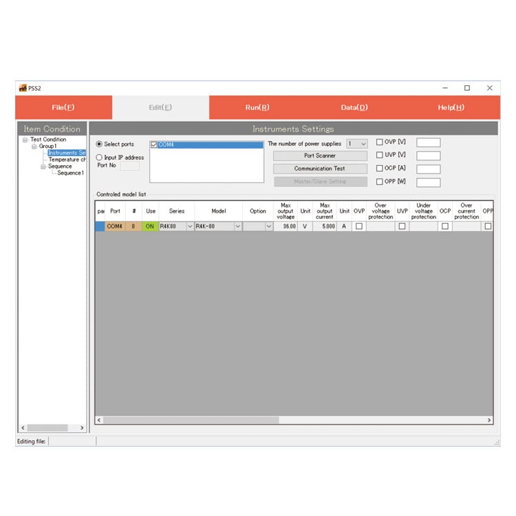
- PSS2en series
-
PSS2en is the dedicated software that can actuate various power supplies, electronic loads, and digital controllers for power supplies manufactured by Matsusada Precision Inc. with a simple setup.
It is perfect for the aging test, the burn-in test and the withstand voltage test for electronic parts, and for the endurance test, intermittent/continuous operation test, or various simulation tests for electric components of automobiles.
For details, refer to PSS2en page.
Dimensions
Download
If you are unable to download a file
Please try the following solution.
- Please press Ctrl+F5 to clear the cache of your web browser and try again.
- Please restart your web browser and log in again to try again.
- Please change your web browser to another browser and try again.
- Restart the computer and try again.
- Please try again on a different computer.
-
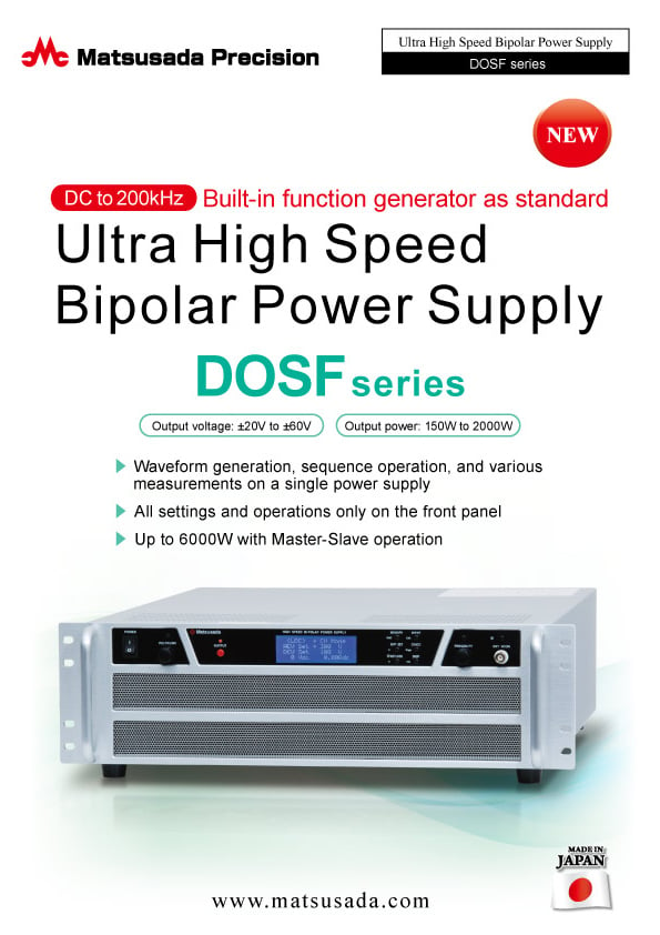
DOSF series Datasheet
Date: 2024-01-16 rev.20
PDF (2,603 KB)
-
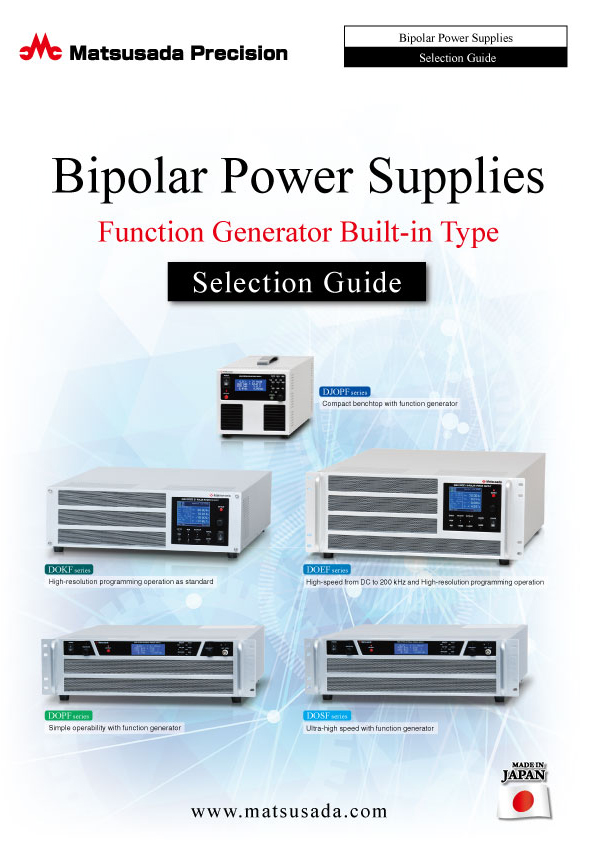
Bipolar Power Supplies with Function Generator
Date: 2025-01-20 rev.06
PDF (4,904 KB)
-
Bipolar Power Supplies/Amplifiers Selection Guide
Date: 2023-10-17 rev.03
PDF (6,310 KB)

-
DOSF series Instruction Manual
Date: 2022-3-23 rev 1.0
PDF (1,694 KB)
-
DOSF series USB Driver
Date: 2025-01-22 rev 1.7.6
ZIP (6,504 KB)
Login Required

-
DOSF series Datasheet
Date: 2024-01-16 rev.20
PDF (2,603 KB)

-
Bipolar Power Supplies with Function Generator
Date: 2025-01-20 rev.06
PDF (4,904 KB)

-
Bipolar Power Supplies/Amplifiers Selection Guide
Date: 2023-10-17 rev.03
PDF (6,310 KB)

-
DOSF series Instruction Manual
Date: 2022-3-23 rev 1.0
PDF (1,694 KB)
-
DOSF series USB Driver
Date: 2025-01-22 rev 1.7.6
ZIP (6,504 KB)
In this website, we provide only the latest version of information including instruction manuals as of our products. Therefore, the newest versions of manuals on the website might be not same as the ones of products you purchased in the past.


