


Piezoelectric actuators excel at precise positioning control at the micron level and offer versatility across numerous applications. However, these actuators come with several important considerations, and proper implementation requires a thorough understanding of these factors during the design phase. In this article, we will provide a comprehensive overview of piezoelectric actuators, including their characteristics and operating principles, along with key design considerations and selection criteria when using them with piezo drivers.
Features of Piezoelectric Actuators
First, let's explore the key features and applications of piezoelectric actuators.
What is a Piezoelectric Actuator?
A piezoelectric actuator is a device that converts electrical signals into physical movement using piezoelectric elements. These elements have the fundamental property of deforming or distorting when voltage is applied, and piezoelectric actuators harness this characteristic for energy conversion.
Although the displacement is extremely small due to the nature of the material's structural changes, this actually enables incredibly precise control at the submicron level. Piezoelectric actuators offer several additional advantages, including high operating frequencies, the ability to generate forces up to several tons, and exceptional longevity due to their lack of moving mechanical components. These characteristics make them invaluable across a wide range of applications, particularly in precise positioning control.
Applications of Piezoelectric Actuators
Let's explore the diverse applications where piezoelectric actuators are commonly used. In industrial settings, these actuators play a crucial role in precision control applications, including positioning optical lenses, aligning optical fiber axes, controlling mask positioning in semiconductor manufacturing equipment, and adjusting specimen positions in electron microscopes. In the consumer market, piezoelectric actuators are widely integrated into digital cameras for autofocus and image stabilization functions, as well as in inkjet printer pumps. Their versatility extends to automotive applications, where they're used in fuel injection pumps, and in devices that generate ultrasonic vibrations, among many other applications.
Types of Piezoelectric Actuators
Piezoelectric actuators can be categorized into several types based on their structure and the piezoelectric materials used. Let's examine the characteristics of each commonly used type.
Piezoelectric Materials
First, let's explore the characteristics of different piezoelectric materials.
Single-crystal Piezoelectrics
Single-crystal piezoelectric elements are manufactured using materials in which the atomic arrangement is completely uniform throughout the crystal structure. Due to this uniform crystalline alignment, these materials exhibit particularly strong piezoelectric effects along specific crystallographic orientations. While quartz and lithium niobate are well-known examples of piezoelectric single crystals, many other varieties exist, and research continues to develop materials with enhanced piezoelectric properties.
Piezoelectric Ceramics
Piezoelectric ceramics are materials created by heating and sintering substances with piezoelectric properties into ceramic forms. When first manufactured, these ceramics have randomly oriented crystals and generate relatively weak forces. Therefore, they undergo a polarization process to align their crystal structure. While their piezoelectric performance is lower compared to single crystals, they offer significant advantages: They're easier to manufacture, and their piezoelectric orientation can be freely adjusted through polarization treatment. Common examples include barium titanate (BaTiO3) and lead zirconate titanate (PZT: A mixed crystal formed from lead titanate (PbTiO3) and lead zirconate (PbZrO3)).
Piezoelectric Thin Films
Piezoelectric thin films are micrometer-scale layers of piezoelectric materials. They are created using deposition techniques, such as sputtering, to apply materials like zinc oxide (ZnO), lead zirconate titanate(PZT), and aluminum nitride(AIN). These thin films have become the most widely used material in ultra-small piezoelectric devices, particularly in MEMS applications.
Actuator Structures
Let's examine the different structural types of piezoelectric actuators.
Multilayer Piezoelectric Actuators
Multilayer actuators are constructed by stacking multiple layers of piezoelectric element, with electrodes attached to each layer. These devices achieve large displacements through the expansion and contraction of each piezoelectric element is in the stacking direction. Their key advantages include achieving significant displacement at low driving voltages, generating substantial forces, and providing excellent high-speed response characteristics.
Bimorph piezoelectric actuators
Bimorph actuators consist of two piezoelectric plates bonded together. When voltage is applied, one plate extends while bending, and the other contracts in the same direction, resulting in an arc-shaped displacement. While these actuators can achieve very large displacements, they generate relatively small forces and have slower response times compared to other types.
Tubular piezoelectric Actuators
Tubular actuators are constructed with cylindrical piezoelectric elements that feature electrodes on both the inner and outer surfaces. These actuators can perform radial displacement (expanding the circumference) and axial displacement (extending lengthwise). When multiple electrodes are arranged on the outer surface, they can achieve bending motion and three-axis displacement. These specialized actuators are commonly used in scanning probe microscopes (SPM/AFM), inchworm motors, and mirror control systems.
Other Types
Beyond the types discussed above, piezoelectric actuators come in many other structural configurations, each designed for specific applications. For example, some designs incorporate mechanical amplification mechanisms with multilayer actuators, using lever principles to achieve larger displacements while maintaining rapid response times. For more detailed information about various piezoelectric actuator designs, please visit the websites of leading manufacturers.
Operating Principles of Piezoelectric Actuators
Let's explore the fundamental principles behind how piezoelectric actuators function.
The Principle of Electric Polarization
What Is Polarization?
The function of piezoelectric elements is based on a phenomenon called "electric polarization." All materials contain positive and negative ions (cations and anions) that maintain electronic balance through their crystalline structure. Materials that exhibit piezoelectric properties have a unique characteristic: When force is applied, their crystal structure shifts, causing a displacement in the relative positions of cations and anions.
When this ionic equilibrium is disrupted, positive charges accumulate on one side and negative charges on the other, creating an electrically polarized state. This polarization generates a voltage difference, which results in the fundamental piezoelectric effect -applying mechanical force to a piezoelectric element generates voltage.
Piezoelectric Effect
When force is applied to a piezoelectric element and generates electrical polarization and voltage, the phenomenon is known as the "piezoelectric effect." One unique characteristic of the piezoelectric effect is its ability to generate electricity without an external power source, making it ideal for applications such as ignition devices in lighters and pressure sensors.
Inverse Piezoelectric Effect
Piezoelectric elements can also generate physical forces, such as pressure and vibration, when voltage is applied. This is known as the "inverse piezoelectric effect" because it works in the opposite direction of the piezoelectric effect. This inverse effect is the principle behind piezoelectric actuators and is also utilized in other applications, such as quartz oscillators for timekeeping and miniature speakers.
Control Using Piezo Drivers
While we've covered the types and characteristics of piezoelectric actuators, their practical implementation requires a driver (piezo driver) for proper control. Let's examine the role of piezo drivers and their control methods.
What Is a Piezo Driver?
A piezo driver is a specialized power-supply device that enables proper operation of piezoelectric actuators. Piezoelectric elements deform in response to applied voltage. While current isn't necessary for low-speed operations, the inherent capacitance of these elements means that current becomes essential for high-speed operations. (You can find specific current requirements in the "Current Value" section below.)
Since piezoelectric elements are capacitive components that require charge extraction, specialized piezo drivers have been developed as dedicated power supplies. Piezo drivers employ two distinct control methods depending on how the actuator is controlled: open-loop control and closed-loop control.
Open-loop Control
Open-loop control determines the required voltage by measuring displacement relative to applied voltage in advance. This straightforward control method offers the advantages of simple structure and low cost. However, it cannot account for displacement non-linearity and hysteresis, nor can it compensate for errors caused by temperature variations and creep phenomena. As a result, the actuator's precision may not be maintained under certain operating conditions.
Closed-loop Control
Closed-loop control is a method where the displacement output of the piezoelectric actuator is fed back to adjust the input accordingly. This system can detect displacement non-linearity and various errors to adjust the power supply, thereby improving the overall accuracy of the piezoelectric actuator.
Displacement Sensors
When implementing closed-loop control, a displacement sensor is required to measure the movement of the piezoelectric actuator.
What Is a Displacement Sensor?
A displacement sensor, as its name implies, is a device that measures the movement or displacement of an object. This sensor can detect not only the distance an object has moved but also dimensional changes, allowing it to accurately measure the displacement caused by piezoelectric actuator deformation.
Types of Displacement Sensors
While various types of displacement sensors exist, three main types are commonly used in closed-loop control of piezoelectric actuators: strain gauges, capacitive sensors, and eddy current sensors.
Strain gauges are devices attached directly to the moving part of the piezoelectric actuator to measure displacement. While they offer a simple structure and good accuracy, they require physical attachment to the actuator.
Capacitive sensors measure displacement by detecting changes in capacitance between the sensor and the target object. Though they allow non-contact measurement, they have two key limitations: They require electrical conductivity between the actuator and sensor, and their accuracy can be compromised by the presence of water or other contaminants.
Eddy current sensors work by generating high-frequency currents in a coil placed near a conductive material, creating eddy currents. These sensors offer non-contact measurement capabilities and are less susceptible to environmental noise compared to capacitive sensors.
Proper Usage Guidelines for Piezoelectric Actuators
To achieve precise operation with piezoelectric actuators, careful handling is essential to prevent malfunctions and unnecessary errors. Let's examine the key considerations.
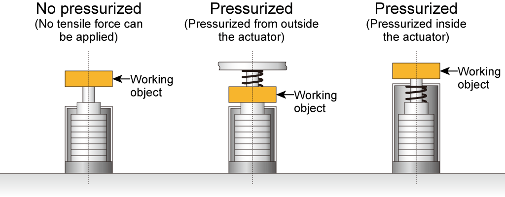
Preload Application
When piezoelectric actuators are used in vibration applications, external forces, such as inertia, can lead to malfunctions. For example, multilayer piezoelectric actuators are particularly vulnerable to forces other than compression along the stacking direction. They can be damaged by tensile forces, bending forces, or even uneven compression forces.
Therefore, in environments where actuators are exposed to various forces from vibration, applying preload pressure by using springs is an effective solution. This preload helps prevent forces from acting in directions other than compression, thereby protecting against damage from external forces.
Stroke Considerations
When the measurement target applies a load to the piezoelectric actuator, the actuator compresses under this load, resulting in a reduced maximum stroke. Therefore, when selecting a piezoelectric actuator, it's essential to choose one with a sufficient maximum stroke that accounts for this load-induced compression.
Current Requirements
To ensure accurate operation of piezoelectric actuators, it's crucial to select a piezo driver capable of supplying sufficient drive current. For sinusoidal operation, the maximum and average current values can be calculated using these formulas:
Maximum Current = Π x Piezoelectric Element Capacitance x Drive Frequency x Drive Voltage
Average Current = Maximum Current x 2/Π
For pulse operation, the current required during voltage rise and fall times can be calculated using the following formula:
Rise/Fall Current = Capacitance x Drive Voltage / Response Time
However, in practice, the actual current requirements vary due to multiple factors, including capacitance tolerances. Therefore, these calculations should be used as general guidelines rather than absolute values.
Operating Temperature Range
Piezoelectric actuators lose their functionality above their Curie temperature, so they must be operated below this critical threshold. The Curie temperature is the point at which thermal energy causes the loss of spontaneous polarization, resulting in the loss of piezoelectric properties. Therefore, for high-temperature applications, it's essential to select products that use piezoelectric elements with higher Curie temperatures.
Load Configuration
Each piezoelectric actuator has its own resonant frequency, but this frequency changes when a load is connected, which can lead to unexpected problems. This is particularly important with heavier loads, as they tend to lower the actual resonant frequency. To prevent issues, the actuator should always be operated at frequencies below its loaded resonant frequency.
Response Speed
When high response speeds are required from piezoelectric actuators, large currents must be supplied to achieve the desired voltage across the piezoelectric element in a short time. The faster the required response, the higher the current demand, so it's crucial to ensure the piezo driver can deliver sufficient current.
Resonant Frequency
As mentioned in the load configuration section, each piezoelectric actuator has its own characteristic resonant frequency. When operating at high speeds, resonance can amplify vibrations and cause unexpected behavior. While datasheets may show high resonant frequencies with apparently adequate margins, the actual resonant frequency can vary significantly depending on factors such as connected loads and mounting methods. A general rule of thumb is to operate at 1/3 to 1/5 of the resonant frequency, but the specific product should be selected based on actual operating conditions.
Important Precautions
It's crucial to note that piezoelectric actuators require an amplifier-type power supply for operation. Since piezoelectric elements are capacitive components, they not only need to source electric power but also must be able to sink current. Standard DC power supplies cannot meet these requirements, so specialized piezo drivers must be used.
Selecting a Piezoelectric Actuator
Let's summarize the key considerations when selecting a piezoelectric actuator as discussed above. Begin by calculating the required stroke and force generation capabilities, taking into account the load-induced compression. For high-speed applications, verify that the capacitance is sufficiently low and the actuator is rated for high-speed operation. Finally, evaluate the voltage-to-displacement linearity (hysteresis characteristics). If strong non-linearity is present or precise control is required, implement closed-loop control. Remember that closed-loop control requires a displacement sensor, so select one appropriate for your application.
Introduction to Matsusada Precision's Piezoelectric Actuators and Drivers
Matsusada Precision offers a comprehensive range of piezoelectric actuators and versatile piezo drivers.
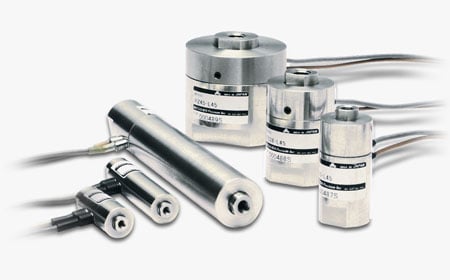
Piezoelectric Actuators
PZ series
The PZ series consists of linear piezoelectric actuators equipped with displacement sensors for high-precision displacement control. With 40 different models available, these actuators can accommodate a wide range of applications. Features include:
- • Integrated displacement sensor (strain gauge)
- • Maximum strokes: 22 μm to 110 μm
- • Maximum force generation: 800 N to 19,000 N
- • High environmental durability with metal package construction
- • 40 different models with varying strokes and power outputs

PZA series
The PZA series achieves nanometer-scale resolution through stacked piezoelectric elements. These linear actuators are available in 45 different models, each with integrated displacement sensors, making this series suitable for various applications. Features include:
- • Integrated displacement sensor (strain gauge)
- • Maximum strokes: 22 μm to 132 μm
- • Maximum force generation: 800 N to 3,000 N
- • High environmental resistance with metal package construction
- • Available in three power levels, five stroke lengths, and three tip configurations

Piezo Drivers
PZJE series
The PZJE series offers desktop-type bipolar piezo drivers. These units can operate large-capacity piezoelectric elements, drive multiple elements in parallel, and handle high-speed sinusoidal wave operations, such as vibration excitation. Key specifications include:
- • Ability to drive a 10 μF piezoelectric element at 100 Hz
- • Rated output voltage: 150 Vdc to 300 Vdc
- • Average output current: 0.3 A to 0.75 A

PZJR series
The PZJR series consists of desktop-type high-power piezo drivers. These units excel at driving large-capacity piezoelectric elements, operating multiple elements in parallel, and managing high-speed sinusoidal wave operations, such as vibration excitation. Key specifications include:
- • Ability to drive a 10 μF piezoelectric element at 900 Hz
- • Rated output voltage: 100 Vdc to 300 Vdc
- • Average output current: 0.67 A to 2.0 A
- • Supports high-speed step drive with 6A peak current

PZJ series
A compact benchtop high-speed piezoelectric driver capable of three-channel output. A single unit can handle multi-axis driving requirements, such as X, Y, and Z coordinates. Features include:
- • Compact benchtop design
- • Support of three-channel piezoelectric drive
- • Ability to drive a 1 μF element with 1.3 kHz sine wave
- • Rated output voltage: 100 Vdc to 300 Vdc
- • Average output current: 0.1 A to 0.3 A

PZJD-0.15 series
A piezoelectric driver capable of high-speed operation with pulse output, supporting large-amplitude drive pulses. Features include:
- • Compact benchtop design
- • High output capacity with 50A peak current and 100mA average current
- • Rated output voltage: 150 Vdc
- • Average output current: 0.1 A

PZJ-S series
A compact benchtop piezoelectric driver equipped with a sensor amplifier for closed-loop control. This driver features enhanced peak power capability, enabling high-speed displacement during pulse operation. Features include:
- • Compact benchtop design
- • Closed-loop control compatibility
- • Peak current capability of 3 times the rated value
- • Rated output voltage: 120 Vdc to 150 Vdc
- • Average output current: 0.1 A to 0.3 A

PZM-0.12BS series
A compact, built-in piezoelectric driver with a sensor amplifier for closed-loop control. Despite its small size, its enhanced peak power design allows it to perform comparably to larger drivers. Features include:
- • Compact module design ideal for equipment integration
- • Closed-loop control compatibility
- • Peak current output capability of twice the rated value
- • Rated output voltage: 120 Vdc

PZM series
A compact module-type high-voltage power supply specifically developed for driving piezoelectric elements. The output can be controlled via external signals. Features include:
- • Compact module design ideal for equipment integration
- • Rated output voltage: 100 Vdc to 1000 Vdc
- • Average output current: 3.3 mA to 30 mA

PZM-B(0.3W) series
A compact onboard module with an integrated power supply and an amplifier designed for driving piezoelectric elements. Enhanced peak current makes it particularly suitable for positioner applications. Features include:
- • Compact onboard design
- • Compatibility with capacitance ranging from 0.01 μF to 10 μF
- • Rated output voltage: 100 Vdc to 300 Vdc
- • Average output current: 1 mA to 3 mA
