X-ray inspection systems are widely used across various industries. Implementing these systems enables efficient defect detection and early identification of potential issues.
In this article, we'll cover everything from the fundamentals of X-rays to practical tips for conducting X-ray inspections. Following this, we'll also showcase some example X-ray images of everyday electronic devices and our range of X-ray inspection systems.
Whether you're looking to learn about X-ray inspection or apply it in your work, we encourage you to read through to the end.
X-Ray Fundamentals
X-ray inspection plays a crucial role in multiple sectors, including the industrial, medical, and food industries. In this section, we'll explain what X-rays are and how they work.
What Are X-rays?
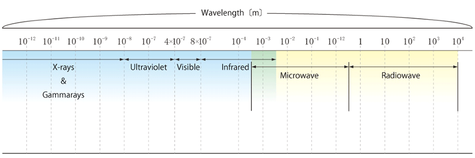
X-rays are a form of electromagnetic radiation. They belong to the electromagnetic spectrum, which includes other types of radiation such as visible light, ultraviolet rays, infrared rays, and microwaves. As shown in the diagram, X-rays have wavelengths that range from 0.001 nm to 10 nm, which is shorter than those of visible light and ultraviolet radiation.
While visible light is blocked by objects, X-rays can penetrate through matter at the atomic level due to their short wavelength and high energy. However, X-rays don't pass through materials completely unchanged-they undergo attenuation during transmission. This occurs because of various interactions (including photoelectric effects, characteristic X-ray emission, and inelastic scattering) when X-rays collide with electrons orbiting atomic nuclei. The X-rays that don't experience these interactions continue traveling in a straight line and become transmitted X-rays. This transmission property is the basis for X-ray imaging, which is used in both medical radiography and non-destructive testing. X-ray computed tomography (CT) takes this further by capturing transmission images from 360 degrees to create cross-sectional and three-dimensional views. In X-ray images, areas with higher transmission appear brighter (white), while areas with more attenuation appear darker (black), similar to how shadows work. The contrast in these images depends on the ratio of X-ray transmission intensity through the object being examined. The contrast is affected by several key factors, including X-ray quality, effective atomic number, material density, object thickness, and scattered X-rays. Due to these various factors, precise control of X-ray quality during exposure is essential for effective imaging.
How X-Rays Are Generated
An X-ray source, also known as an X-ray tube, is a vacuum tube designed to generate X-rays.
The generation process begins by passing an electrical current through a filament to heat it up. This heating causes the filament to emit thermal electrons, a phenomenon known as thermionic emission (first discovered by Edison during his research on incandescent light bulbs). These electrons are then accelerated using high voltage and directed to collide with a target on the anode. It's worth noting that less than 1% of these thermal electrons actually convert into X-rays, with the majority of the energy being transformed into heat.
X-ray sources come in various configurations, featuring different shapes and power supply connection methods. They serve numerous applications, with medical X-ray equipment being one of the most common uses.
At Matsusada Precision, we've developed integrated high-voltage power supplies for X-ray tubes that combine both the filament power supply and the acceleration high-voltage power supply. This integration enables us to achieve two seemingly contradictory goals: compact equipment size and high-energy X-ray output.
Basics of X-Ray Inspection
In this section, we'll explore the various applications and significance of X-ray inspection across different sectors.
Role of X-Ray Inspection
X-ray inspection has revolutionized manufacturing processes by enabling the internal observation of products and objects without the need for destruction or disassembly. As its name suggests, non-destructive testing allows for product inspection while keeping items fully intact. This inspection technology enables us to examine internal defects and deterioration without dismantling or damaging the products, making it an invaluable tool for quality control and lifespan assessment. Companies that implement X-ray inspection systems benefit from significant cost reductions and enhanced accident prevention through early detection of potential issues. Beyond manufacturing, X-ray inspection plays a vital role in our daily lives, particularly in medical diagnostics and food safety.
Fields of X-Ray Inspection Applications
X-ray inspection technology has been adopted in various sectors, finding essential applications in the following main areas.
Industrial Applications
X-ray inspection plays a vital role in manufacturing quality control, examining welded joints in automotive parts, solder connections in electronic components, and inspecting resin-molded products and precision castings. It's particularly valuable for examining glass products such as high-intensity discharge lamps, as traditional visible light inspection is hampered by reflections. The technology is also essential for inspecting high-density component assembly in ICs and printed circuit boards. These applications significantly enhance quality control, safety assurance, operational efficiency, and overall business performance.
Medical Device Industry
In the medical sector, X-ray inspection is crucial for examining the internal structures of devices such as pacemakers, artificial joints, and catheters. This technology has become indispensable for advancing medical care and ensuring the reliability of medical devices, ultimately contributing to better healthcare outcomes.
Food Industry
Food manufacturers rely on X-ray inspection to detect foreign contaminants such as metal fragments and plastic pieces within food packages. This application is crucial for maintaining quality control, ensuring food safety, and optimizing production efficiency.
Additional Applications
The versatility of X-ray inspection extends far beyond these primary sectors. It serves essential roles in research and development, forensic investigation, art authentication, reverse engineering, structural analysis of buildings and infrastructure, security screening, agricultural applications, seed inspection, archaeological studies, and geological surveys. The technology has become so deeply integrated into various aspects of modern society that it's now an essential tool in our daily lives.
Tips for X-Ray Imaging
This chapter explores the essential parameters to configure before conducting X-ray imaging and examines how different settings affect image quality. We'll also cover image processing and analysis techniques, as well as important factors that can introduce errors in captured images.
Imaging Parameters
Before conducting X-ray imaging, it's crucial to understand various X-ray parameters and how equipment settings influence image quality. The quality of X-ray images is significantly affected by adjustable parameters such as X-ray wavelength (controlled by tube voltage) and radiation dose (controlled by tube current), making it essential to understand these relationships. We'll explore these aspects in detail below.
Note that when selecting an inspection system, several other parameters must be predetermined based on the imaging target, including monitor magnification, field of view, focal spot size, and irradiation method.
Setting Voltage and Current Parameters
Achieving clear X-ray images requires careful adjustment of X-ray tube voltage and current based on the subject's size, material composition, and structure. Let's explore how these parameters work and affect image quality.
Tube voltage refers to the electrical potential applied across the X-ray tube. In the tube, a high-voltage power supply connects the cathode (-) and anode (+), accelerating electrons from the cathode to collide with the anode, generating X-rays. Higher tube voltage produces X-rays with shorter wavelengths that penetrate materials more easily. The total X-ray intensity increases proportionally to the square of the tube voltage.
The tube current is the electrical current flowing through the X-ray tube. When thermal electrons generated by the filament collide with the anode, they create an electrical current. Increasing the tube current raises the X-ray dose, though this doesn't affect the minimum wavelength (maximum energy). The total X-ray intensity increases linearly with tube current. When tube voltage alone cannot optimize image quality, fine adjustments can be made by controlling tube current through the filament temperature.
While it might seem logical to set a high tube voltage for better penetration, this can sometimes result in excessive penetration and poor contrast. In such cases, increasing the tube current can produce brighter images by raising the X-ray dose. Maintaining low noise levels is crucial throughout this process. Increasing either tube voltage or current can enlarge the focal spot, potentially causing image blurring during magnification. Matsusada Precision's microfocus X-ray tubes address this issue by utilizing a micrometer-sized focal spot (where X-rays are generated), producing clear magnified images without blurring. For CT imaging, it's essential to verify image quality at the angle at which X-ray penetration is most challenging.
Adjusting Exposure Time
Image quality can be enhanced by modifying the subject's exposure time during X-ray imaging. Longer exposure times enable the capturing of high-resolution images with greater detail. When a high resolution isn't essential, shorter exposure times can be used, offering the benefit of reduced inspection time.
For CT scanning, there are two primary methods. If the stage rotation is stopped after each shot for intermittent X-ray exposure, longer imaging times can be achieved, resulting in higher-resolution images. Alternatively, continuous X-ray exposure without stopping the stage rotation can significantly reduce the overall scanning time.
Subject Characteristics in X-Ray Imaging
X-ray imaging requires selecting appropriate imaging methods based on the subject's characteristics and size. Understanding how X-rays interact with different materials is crucial for achieving optimal results.
Material Density Effects
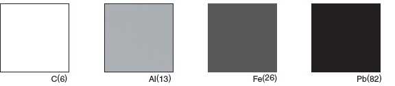
The transmission of X-rays varies significantly depending on the material's density. This variation is determined by three key factors: the constituent elements of the material, its thickness, and the proportional composition of these elements. Materials with higher atomic numbers and densities block more X-rays, resulting in darker (blacker) areas in the final image. It's important to note that variations in density can sometimes introduce errors in the captured images.
When X-rays are directed through an object, measuring the intensity of transmitted radiation enables us to visualize internal structures that are otherwise invisible from the outside. This process works because X-ray transmission rates change based on the material's density and thickness. By measuring and imaging these transmission rates, we can clearly distinguish between different materials and structural variations within the subject. This capability makes X-ray imaging particularly valuable for detecting abnormalities and defects in terms of both medical diagnostics and industrial applications.
Material Properties of the Subject
X-ray transmission rates vary depending on the material's density. High-density materials, such as metals, exhibit higher attenuation rates, while low-density materials, such as air and paper, allow more X-rays to pass through, resulting in lower attenuation rates.
As mentioned earlier, materials with higher atomic numbers shield more X-rays. For instance, when comparing plastics and metals, metals typically require higher tube voltages for penetration due to their higher atomic numbers and they appear darker in the resulting images. Below is an X-ray image of a ball grid array (BGA) that illustrates these principles.
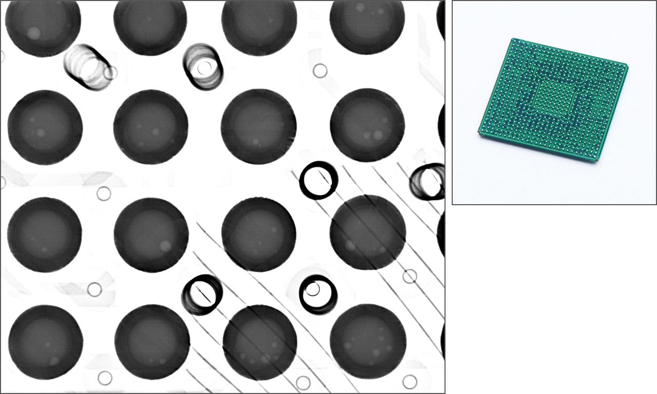
Image Processing and Analysis
In this section, we'll explore the fundamentals of image processing, including contrast adjustment and three-dimensional analysis techniques.
Image Processing Fundamentals
X-ray imaging uses specialized detectors called X-ray flat panel detectors (FPDs) that convert transmitted X-rays into electrical signals to produce images. Modern X-ray cameras predominantly use flat-panel technology with 8-bit or higher grayscale capabilities. Since computer displays are typically limited to 8-bit grayscale, range adjustment is often necessary.
A key distinction exists between traditional X-ray imaging and CT. While standard X-ray imaging provides a perspective view from the direction of X-ray irradiation, CT generates cross-sectional images of objects from any desired angle. In traditional X-ray inspection, the transmitted X-rays directly form the image. CT, however, works differently.
CT systems create three-dimensional images by collecting X-ray data from multiple angles. This is achieved by rotating the specimen during imaging to capture 2D X-ray images from various directions.
The system then processes these 360-degree rotation images to construct cross-sectional and three-dimensional views. Unlike conventional X-ray images that lack height (thickness) information, CT data can be viewed from any angle and display cross-sections at any position.
The CT reconstruction process involves sophisticated computer processing of the tomographic images. During this reconstruction phase, the system corrects for various factors, including the physical limitations of the CT system, sample characteristics, and measurement methods, and compensates for errors and noise that occur during data processing. Next, we'll examine methods for contrast adjustment and three-dimensional analysis.
Adjusting Contrast and Brightness
Image contrast adjustment is achieved by optimizing gamma values and luminance ranges, while brightness is controlled by adjusting gain values and tone curves. During imaging, depending on the scanning conditions and subject material, secondary images called artifacts may appear in the image that don't correspond to actual physical objects. As previously discussed, material density directly correlates with X-ray attenuation rates, which can affect image brightness and, consequently, contrast. When imaging composite materials, a specific type of artifact known as metal artifacts can appear as continuous noise patterns around metallic components. These artifacts can be minimized through two main approaches: implementing reduction techniques during the CT scanning process and applying corrective measures during image processing (reconstruction).
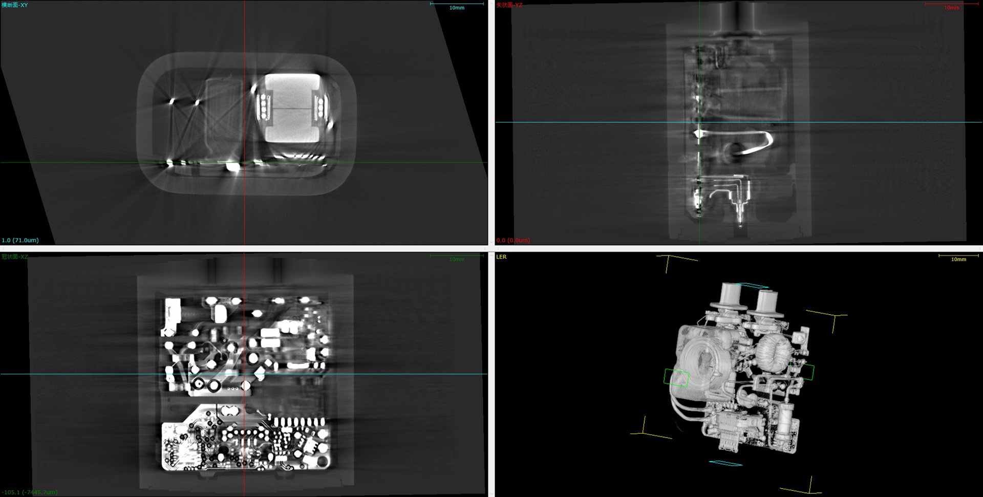
Three-Dimensional Analysis Using Software
Converting multiple 2D X-ray images into 3D reconstructions enables sophisticated three-dimensional analysis using specialized software. The reconstructed CT data is displayed through multiplanar reconstruction (MPR), which transforms volume-rendered images into cross-sectional views from three directions and creates three-dimensional visualizations. CT analysis software offers a comprehensive suite of capabilities, including image processing features such as reconstruction and metal artifact reduction and 2D/3D visualization and analysis tools. Users can view arbitrary cross-sections, perform dimensional measurements, and calculate volume and surface area measurements.
The Geometric Dimensioning and Tolerancing (GD&T) functionality enables detailed analysis using 3D data, including design value/actual measurement comparisons, defect analysis, and wall thickness measurements.
These tools are valuable for examining the internal microstructures of various materials and products in three dimensions, including plastic moldings, metal components, electronic parts, electronic devices, pharmaceuticals, containers, and biological specimens.
While CT technology offers numerous advantages, achieving optimal imaging results requires significant expertise and experience.
Examples of X-Ray Imaging of Electronic Devices
Here, we showcase various examples of X-ray imaging applications for electronic devices, demonstrating how this technology can be applied to products of diverse types and dimensions.
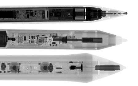
Comparative Analysis: Apple Pencil vs. Surface Pen vs. Wacom Tablet Pen
The Apple Pencil, known for its sophisticated features, such as its tilt and pressure sensitivity that enables smooth writing, reveals a densely packed internal structure under X-ray examination. Among the three styluses examined, the Apple Pencil has the highest component density.
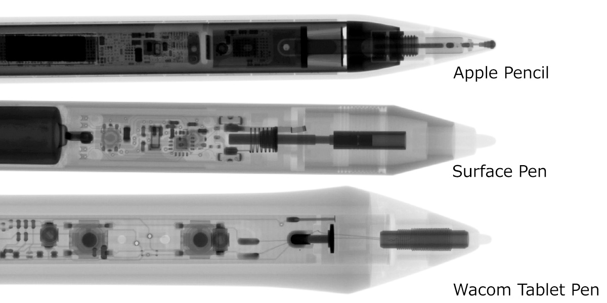
In the detailed X-ray image focusing specifically on the Apple Pencil, we can clearly observe not only the abundance of internal components but also their intricate details with remarkable clarity.

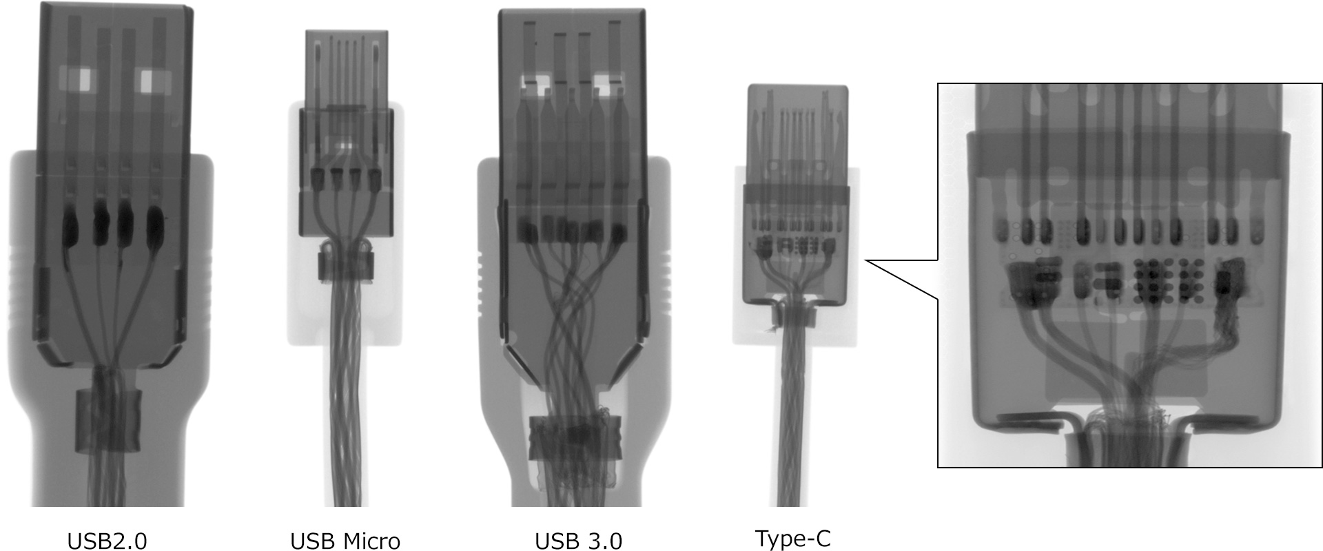
USB Cable Analysis
The X-ray images compare four different USB cables (from left to right): USB 2.0, USB Micro, USB 3.0, and Type-C cables. These represent the standard USB connector configurations: Type-A, Micro-B, Type-A, and Type-C, respectively. The X-ray examination reveals their internal structures, showing that USB 2.0 and Micro USB have four buses each, while USB 3.0 and Type-C feature six buses. The size comparison shows that Type-A has the largest, followed by Type-C, then Micro-B. A distinctive feature of the Type-C connector is the presence of an internal circuit board, which is clearly visible in the X-ray image.
Various Battery Types
The X-ray comparison shows images of four different batteries arranged from left to right: an AA-size manganese battery, an alkaline battery, a nickel-metal hydride (rechargeable) battery, and an 18650-size lithium-ion battery (rechargeable, not commercially available).


| Battery Types | Structural Characteristics |
|---|---|
| Manganese battery | The key structural difference between manganese and alkaline batteries is visible in their current collectors. In the X-ray image, the materials surrounding the current collector (manganese and zinc) show varying darkness, with zinc appearing darker due to its higher atomic number. |
| Alkaline battery | |
| Nickel-metal hydride battery | This battery features an insulating tube wrapped around its negative electrode. Due to its nickel composition, the negative electrode appears darker in X-ray images at the same exposure level. |
| Lithium-ion battery | The internal structure consists of alternating layers of cathode plates, anode plates, and separators, all contained within an outer case. |
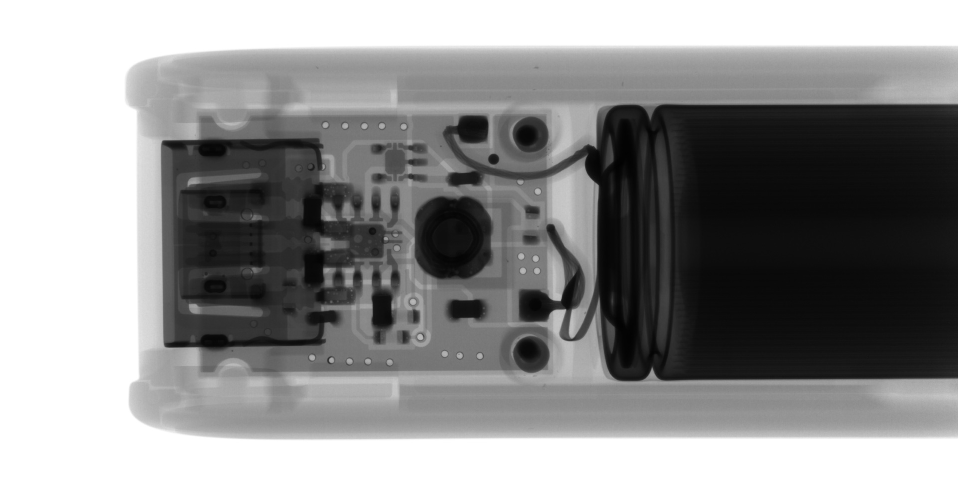
The X-ray image of the novelty mobile battery charger reveals its internal components from left to right: the USB terminal, circuit board, and socket. The detailed scan clearly shows the wiring connections between the circuit board and socket, as well as the circuit board's through holes and internal wiring patterns.
Wireless Charger vs. Smartphone
The X-ray images reveal the internal structures of both devices.
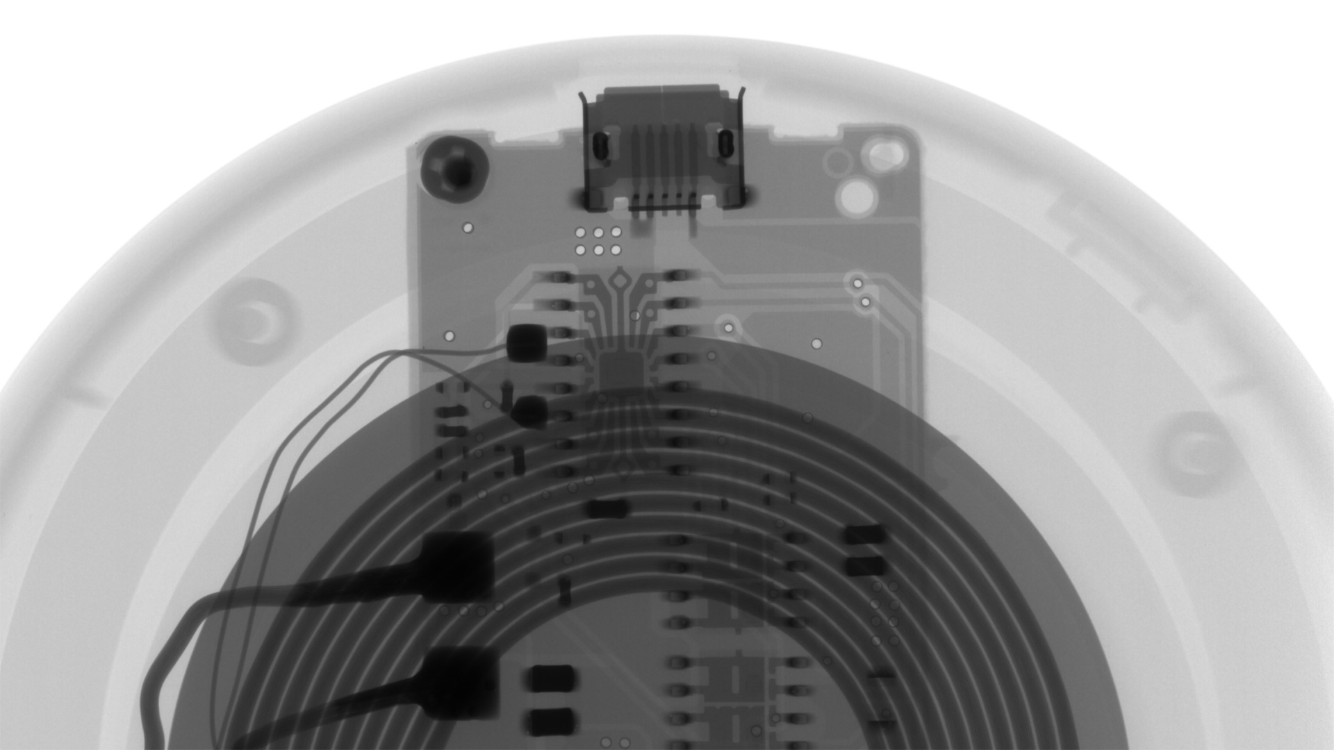
Wireless charging operates without physical connections, utilizing electromagnetic induction through coils. When current flows through the transmission coil in the charger, it generates a magnetic field. Placing a smartphone within this field induces current in the phone's receiving coil, converting magnetic energy into electrical power for charging.
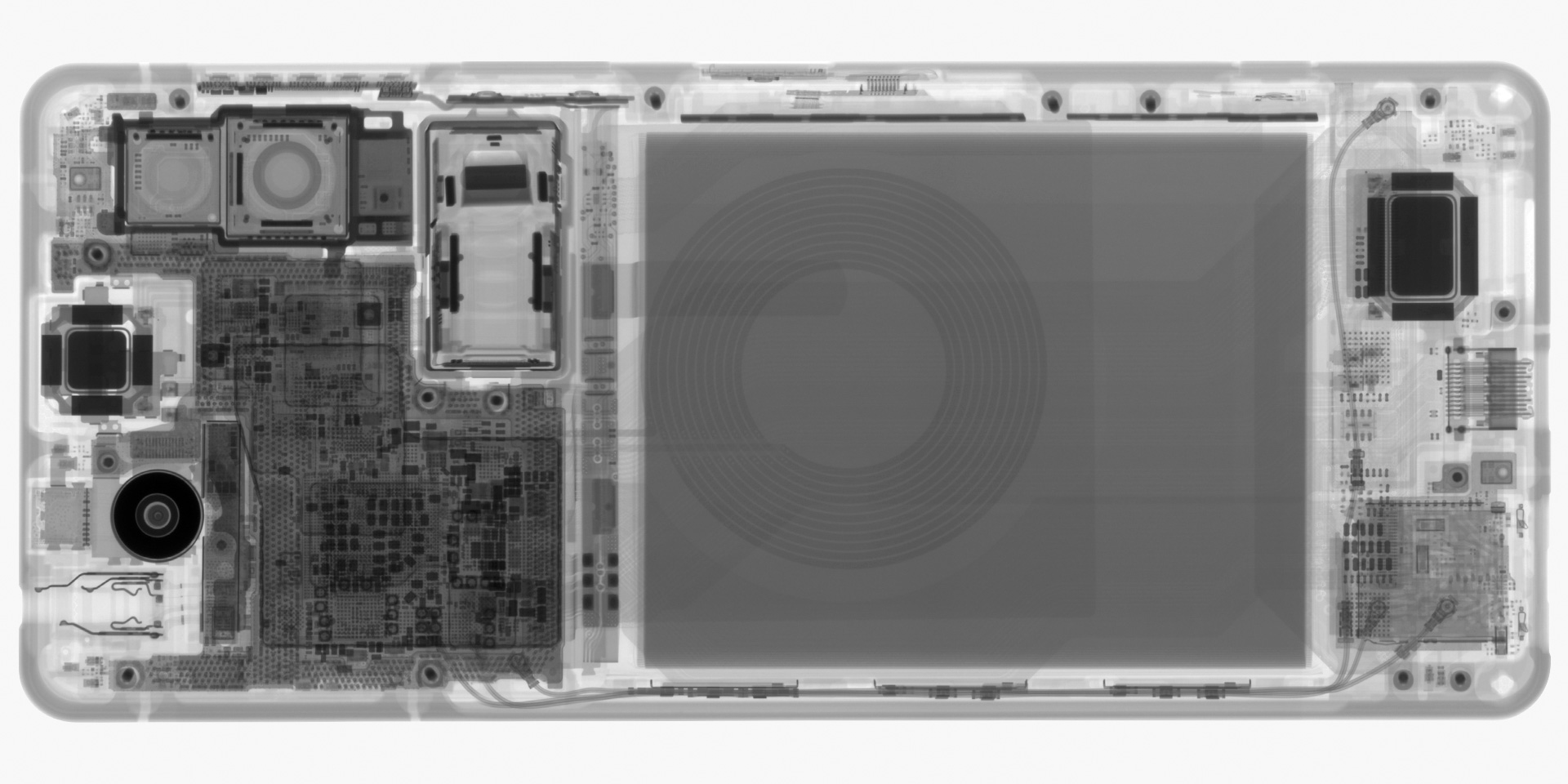
The smartphone image clearly shows various components including the lens, antenna, display, circuit board, and connectors, with detailed visibility of circuit board holes and electronic components, including ICs.
AC Adapter
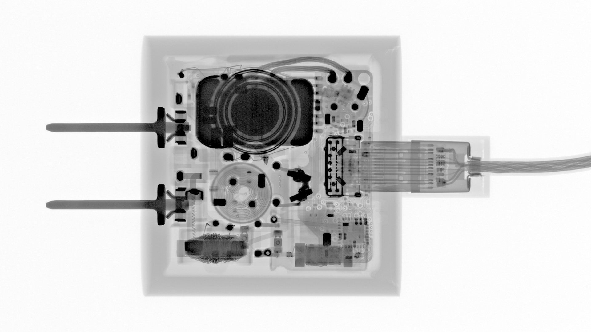
The X-ray scan of Apple's genuine A1720 charger (18W, USB-PD-compatible) shows the circuit board, the AC pins for outlet connection on the left, the connector on the right, and the cord arrangement. The high-resolution image clearly shows the details of the internal circuit board components.
Introduction to Matsusada Precision's X-Ray Equipment
Matsusada Precision offers a comprehensive range of X-ray inspection systems, specializing in non-destructive testing equipment that enables internal observation of electronic devices for quality control purposes. The company has developed proprietary microfocus X-ray tubes using advanced high-voltage technology, enabling high-definition 3D CT imaging and automated defect detection. As a leading manufacturer of industrial X-ray non-destructive testing equipment and CT scanners, Matsusada provides solutions across all price points, from cost-effective systems to high-end equipment. These systems significantly improve efficiency in defect analysis and inspection processes for companies that implement them. Drawing on years of refined expertise, Matsusada Precision's X-ray inspection systems achieve industry-leading image quality through innovative hardware and software technologies. Beyond standard 2D fluoroscopic imaging, the company offers advanced CT scanning capabilities for three-dimensional analysis, particularly useful for examining semiconductor wire bonding and delamination issues. Matsusada's comprehensive product line includes complete X-ray CT inspection systems.
The company offers both vertical and horizontal X-ray irradiation methods, with the specific differences outlined below.
| Irradiation Method | Characteristics |
|---|---|
| Vertical irradiation systems | While requiring greater vertical clearance, these systems offer space-efficient installation. They are available in both desktop and floor-standing models. |
| Horizontal irradiation systems | These systems require more floor space but excel at accommodating larger and heavier specimens. |
The selection of X-ray inspection equipment depends primarily on the specimen's characteristics, including its size, weight, and, in some cases, shape. Key considerations in choosing an inspection system include the X-ray tube's voltage (acceleration voltage) and the test object's composition (constituent elements), thickness, and overall dimensions.
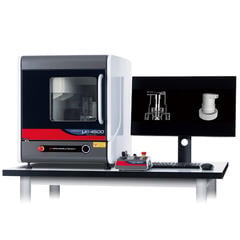
Desktop X-Ray Transmission Inspection Systems (Vertical Irradiation Type)
These compact desktop systems enable non-destructive internal observations of objects, particularly suitable for examining small specimens via methods such as BGA void inspection. Through Matsusada Precision's advanced high-voltage power supply technology, we've achieved an unmatched compact design. Our product range includes affordable models with mini-focus X-ray tubes and high-performance models featuring micro-focus X-ray tubes for high-resolution imaging.
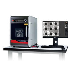
precision µB3600
By incorporating our proprietary high-voltage power supply (developed by Japan's leading high-voltage power supply manufacturer) and specially designed X-ray tube, this desktop unit delivers magnification and power comparable to floor-standing systems. It can effectively examine small, difficult-to-penetrate specimens that traditionally required larger equipment.
precision µB4600
This desktop X-ray inspection system is designed for manufacturing environments, featuring a large 330 x 340 mm stage that enables the inspection of M-size circuit boards despite its compact footprint. Equipped with a high-power X-ray tube, it provides superior penetration capabilities, handling specimens that typically challenge desktop systems. The manual stage control ensures straightforward operation and excellent usability.
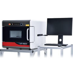
| precision µB3600 | precision µB4600 | |
|---|---|---|
| Tube voltage | 30-90 kV | 40-90 kV |
| Maximum monitor magnification | 136x | 6.0x |
| Dimensions | 455 mm (W) x 625 mm (D) x 630 mm (H) | 685 mm (W) x 750 mm (D) x 585 mm (H) |
| Field of view | 2.6 mm (X) x 2.3 mm (Y) to 4.9 mm (X) x 4.3 mm (Y) | 58 mm (X) x 51 mm (Y) |
X-Ray Transmission Inspection Systems (Vertical Irradiation Type)
These general-purpose X-ray inspection systems enable high-magnification, non-destructive internal observations of objects. Capable of handling specimens of all sizes, including large printed circuit boards, these systems feature large motorized stages for easy examination of target areas. Models equipped with tilt and rotation capabilities allow for 360-degree observations.
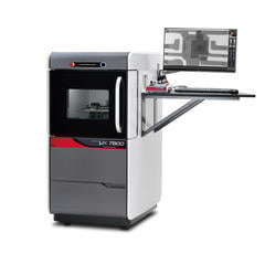
precision µX7800
While being one of the industry's most compact stationary microfocus X-ray inspection systems, this model achieves higher magnification than its predecessors. Using our exclusively developed high-voltage power supply and proprietary X-ray tube, it combines a compact design with high magnification capabilities and offers a wide field of view (X81 x Y46 mm).
precision µX8600
This system features a tiltable X-ray camera that enables imaging from various angles. Its large stage accommodates sizeable specimens, while the 130 kV tube voltage provides substantial penetration power. Despite its compact design, it offers versatility for a wide range of inspection requirements.
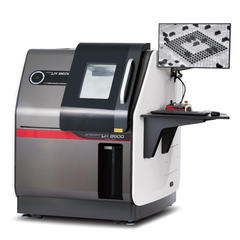
| precision µX7800 | precision µX8600 | |
|---|---|---|
| Tube voltage | 30-90 kV | 40-130 kV |
| Maximum monitor magnification | 176x | 202.4x |
| Dimensions | 726 mm (W) x 895 mm (D) x 1400 mm (H) | 1155 mm (W) x 1330 mm (D) x 1440 mm (H) |
| Field of view | 3.1 mm (X) x 1.8 mm (Y) to 81.4 mm (X) x 45.9 mm (Y) | 2.7 mm (X) x 1.5 mm (Y) to 51.9 mm (X) x 29.3 mm (Y) |
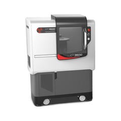
X-Ray CT Scanning Systems (Horizontal Irradiation Type)
Industrial X-ray CT scanning systems, also known as micro CT or X-ray microscopes, provide non-destructive visualizations of internal structures. These systems generate high-precision CT images using detailed X-ray transmission images captured by a microfocus X-ray source. Matsusada Precision's CT scanning systems operate by placing specimens on a turntable and irradiating them with X-rays from the side, capturing transmission images at different angles as the table gradually rotates. A high-performance computer then reconstructs these images to quickly generate detailed CT images. The accompanying software enables various analyses, including arbitrary cross-sectional observation, measurements, and reverse engineering applications.
Matsusada Precision offers two main models, the desktop precision μB4500 and the precision CT9600, which features fully automatic settings for user-friendly CT imaging. Our proprietary technology enables the three-dimensional examination of microscopic internal structures across various materials, including plastic moldings, metal components, electronic parts, electronic devices, pharmaceuticals, containers, and biological specimens.
precision μB4500
This high-specification desktop microfocus X-ray system uniquely combines both transmission imaging and CT scanning capabilities in a single unit. Unlike conventional vertical irradiation systems, its horizontal irradiation design enables easy observation of specimens containing liquids or powders by simply placing them on the stage. The system's error reduction function produces clear images even with mixed-material specimens with different X-ray transmission rates. Despite its compact design, it accommodates large specimens and its partially opening top panel allows for smooth handling of tall specimens.
precision CT9600
This industrial micro-CT system balances precision with speed. Its sophisticated design enables high-quality, high-speed 3D visualizations through simple operation. Using microfocus X-ray technology and a high-resolution camera, it provides micro-level internal visualizations to support rapid problem-solving. Additional features include optimized X-ray irradiation methods for reduced scanning times, image quality correction capabilities, and various efficiency-enhancing functions, all accessible through a user-friendly interface.
| precision μB4500 | precision CT9600 | |
|---|---|---|
| Tube voltage | 30-90 kV | 40-130 kV |
| Maximum monitor magnification | 63.5x | 245.2x |
| Dimensions | 570 mm (W) x 665 mm (D) x 625 mm (H) | 910 mm (W) x 800 mm (D) x 1210 mm (H) |
| Field of view | 8.5 mm (X) x 4.8 mm (Y) to 70.6 mm (X) x 39.8 mm (Y) | Maximum scan area: 70 mm diameter x 34 mm height (in normal scan mode) |
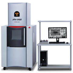
X-Ray Microscopes
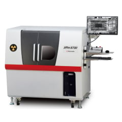
μRay8400 series (Vertical Irradiation Type)
This system features powerful 130 kV tube voltage penetration capabilities, easily imaging metal-encased specimens. Its generous 450 mm-deep stage and accessible door design facilitate smooth specimen handling. Comprehensive hardware and software support functions ensure safe and straightforward operation, even for novice users. The system can be equipped with CT functionality, enabling efficient lot and 100% inspection capabilities.
μRay8700/μRay8760 (Horizontal Irradiation Type)
These high-penetration X-ray inspection systems offer CT scanning capabilities. Combining 130 kV tube voltage penetration power with an output of up to 40 W, they deliver superior image clarity for enhanced transmission observation. Our proprietary noise reduction technology achieves a minimum 5 μm focal spot size at a 4 W output. The microfocus X-ray tube provides remarkable low-noise and high-contrast imaging. These advanced imaging technologies, coupled with feature-rich specialized software and refined user interfaces, enable high-quality non-destructive inspection.