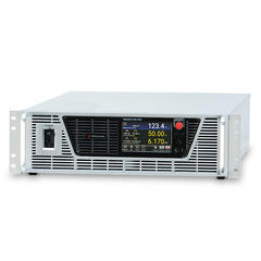
When testing the performance of DC switching power supplies, solar power systems, fuel cell devices, or batteries it's essential to evaluate the quality of the power source. "Power quality" involves multiple factors, requiring electronic loads to have various functions and capabilities to address these different needs.
Understanding the role of electronic load devices in power supply performance testing is the key to ensuring accurate and reliable quality assessments.
This section overviews the fundamental principles, types, and applications of electronic load devices.
What is an Electronic Load?
Electronic loads are widely used in the performance testing of DC power supplies. However, due to their specialized nature, it's important to understand the fundamentals before exploring their different types and applications.
In this section, we will go through the basic concepts of electronic load devices and examine the key reasons they are essential in power supply testing.
Fundamentals of Electronic Loads
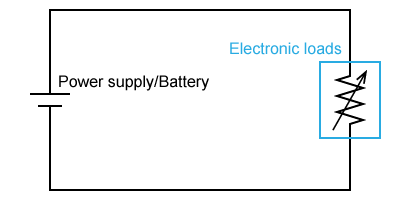
Electronic loads primarily consist of components such as transistors and FETs (Field-Effect Transistors). While many people may associate circuit loads with AC loads like resistive or LC (inductor-capacitor) loads, electronic loads operate similarly but use electronic circuits as substitutes.
Because these loads incorporate transistors or FETs, they provide capabilities beyond those of traditional resistive or LC loads. Users can utilize the device's display settings to perform rapid on-off switching, adjust resistance values linearly or intermittently, and execute other operations that are not possible with conventional loads.
Why Electronic Loads Are Important
Performance testing of DC power supplies involves applying various load patterns to verify the system's response, such as determining whether it can maintain a constant voltage when load resistance fluctuates. Using resistive or LCR loads for these tests may not always allow for easy adjustment of resistance values. Additionally, many DC power supply tests require operations that resistive loads cannot support, such as rapidly changing resistance from very low values to near infinity within a specific timeframe.
Electronic loads offer significant advantages for performance testing. They enable testing under conditions that are difficult to replicate with physical loads like resistive or LCR loads. While LCR loads require rewiring and replacing components to adjust capacity between tests, a single electronic load can perform a series of tests without these modifications.
In recent years, DC power supplies have become essential to our society's infrastructure. They power a wide range of systems, from HVDC (High Voltage Direct Current) setups in data centers to solar power installations and even the batteries in our computers and smartphones. As a result, performance testing of DC power supplies is now more crucial than ever.
Types and Principles of Electronic Loads
Electronic loads provide a range of fundamental modes, each designed for specific performance tests. These operational modes are enabled by electronically controlling transistors and FETs, which allows them to act as loads with dynamically adjustable resistance values.
In the following sections, we'll explore each mode and its underlying operating principles.
Power Consumption and Power Regeneration Types
Electronic loads are classified into two categories based on how they handle power consumption during testing. The first category is the power consumption type, which operates similarly to conventional loads. In this type, the power entering the electronic circuit is dissipated as heat. The primary difference lies in the electronic control of the process. While the energy flow resembles that of a standard load, the power is consumed solely for testing purposes, which can have environmental implications due to energy waste.
The second category is the power regeneration type. In this approach, the power used during testing is redirected back to the reusable AC Line Power through a regenerative circuit within the electronic load device. This creates a power circulation system where energy flows from the power supply to the electronic load and then back to the source. As a result, only the system losses are consumed, significantly reducing overall energy consumption.
Constant Current (CC) Mode
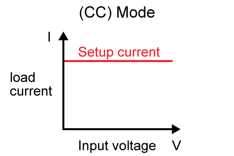
Constant current mode is a functionality that allows an electronic load to maintain a set current flow, regardless of changes in input voltage. In a conventional resistive load, the current would fluctuate with variations in input voltage. However, in constant current mode, the electronic load automatically adjusts its internal resistance to sustain a steady current flow. This adjustment is achieved through dynamic control mechanisms that compensate for voltage variations. The constant current (CC) mode is particularly useful in performance testing of DC switching power supplies, where maintaining maximum current flow across a wide range of voltages is crucial.
Constant Voltage (CV) Mode
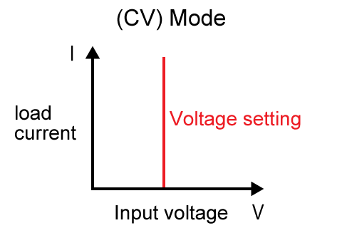
Constant voltage mode is a control mechanism that adjusts the current to maintain a preset voltage at the input of the electronic load. When the input voltage exceeds the set value, this mode increases the current flow to reduce the voltage. Conversely, if the input voltage falls below the set point, it decreases the current to raise the voltage. Unlike a standard resistive load, where voltage fluctuations occur with changing load currents, the constant voltage (CV) mode automatically adjusts the resistance to keep the input voltage constant based on the current load and input voltage.
This functionality is analogous to a Zener diode in electronic components; however, electronic loads can handle a much broader power range, typically from tens of watts to several kilowatts. This capability is especially beneficial in motor applications, where deceleration can generate voltages that exceed the input voltage. By absorbing this excess voltage, the electronic load can prevent damage to control circuits.
The CV mode is also valuable for performance testing devices like battery chargers, where stable output voltage is crucial despite load fluctuations.
Constant Power (CP) Mode
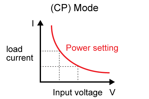
In constant power mode, the electronic load regulates its current to maintain a consistent power consumption level. The device calculates the product of the input voltage and current, comparing it to the power setting. If the result exceeds the set value, the current is reduced; conversely, if it's lower, the current is increased. Achieving this mode with ordinary resistors alone is challenging, as it requires more complex control compared to constant current (CC) and constant voltage (CV) modes.
Constant power mode is particularly useful for measuring the power characteristics of power supplies or batteries during heat generation, as well as assessing the power conversion efficiency of power supplies through testing.
Constant Resistance (CR) Mode
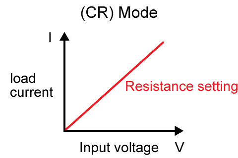
Constant resistance mode allows an electronic load to maintain a fixed resistance value in response to input. Although this may seem similar to a standard resistive load, a key difference exists. In resistive loads, current flowing through the conductor generates heat, causing temperature changes that alter the resistance value. These fluctuations can introduce errors during performance testing. By using an electronic load, the circuit can be treated as if it has an ideal pure resistance connected, effectively eliminating temperature-induced variations.
CC + CV Mode
This mode combines constant voltage and constant current settings for testing purposes. It operates in constant voltage mode until the current reaches a predetermined set value. Once this threshold is met, the mode automatically transitions to constant current operation.
CR + CV Mode
This mode utilizes both constant resistance and constant voltage settings for testing. It begins in constant voltage operation when the set voltage is at or below the supply voltage. If the current exceeds a specified threshold, the mode automatically switches to constant resistance operation.
CP + CV Mode
This mode incorporates both constant power and constant voltage settings for testing. It facilitates complex operations by automatically switching between constant voltage and constant power modes at user-defined points, allowing for flexible and comprehensive testing scenarios.
Multi-mode
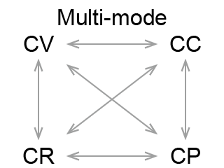
A multi-mode electronic load device can seamlessly switch between the four aforementioned modes to meet various testing requirements. These high-performance devices, equipped with microcontrollers, are capable of handling a wide range of performance tests that utilize all four modes.
VI Mode
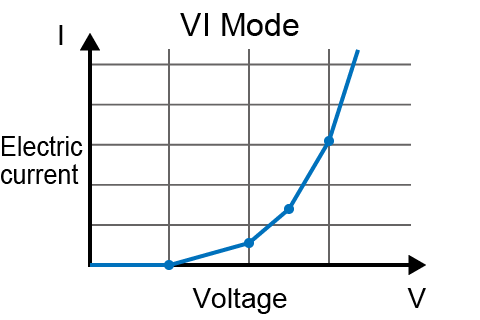
In VI mode, users can set the current flow for each voltage level in relation to the input voltage. This mode can simulate components with nonlinear voltage-current characteristics, such as light-emitting diodes (LEDs) used in lighting applications. By utilizing VI mode, electronic loads can simplify the performance testing of power supplies designed for loads with nonlinear characteristics.
Short Mode
This mode adjusts the electronic load's resistance to as close to zero as possible, simulating a short-circuit condition. Although it mimics a short circuit, a minimal resistance remains connected to ensure safety. This mode is primarily used for conducting short-circuit tests on power supplies.
Applications of Electronic Loads
Now that we have covered the modes and characteristics of electronic loads, let's examine their specific testing applications.

Power Supply Load Regulation Test
The power supply load regulation test is intended to verify that voltage and current fluctuations stay within specified limits, even as the load connected to the power supply changes. To ensure stable output from the power supply unit, loads within the product's specified range are connected to confirm that the power supply's voltage and current align with the expected output. This test is commonly used in evaluation procedures for devices like automotive DC motors, allowing for the simulation and assessment of their ability to respond accurately to sudden load fluctuations.
Rechargeable Battery Discharge Test
This test evaluates the discharge characteristics of rechargeable batteries by connecting them to an electronic load device operating in constant current mode and analyzing their output voltage characteristics. In addition to standard constant current mode testing, pulse current load discharge tests can also be conducted using programmed control of the electronic load device.
Simulated Loads for Automotive ECUs
Automotive ECUs (Electronic Control Units) are CPUs utilized in vehicles for systems such as autonomous driving. After programming, these ECUs undergo performance testing. Before installation in a vehicle, they are subjected to simulated tests that detect changes in resistance values connected to the ECU, mimicking conditions encountered during autonomous driving. Throughout this process, the constant resistance mode is employed for precise performance verification, as it acts as an error-free pure resistance.
Fuel Cell Performance Tests
Electronic load devices with adjustable resistance values are employed in evaluation tests to assess the load response of fuel cells. The primary advantage of these devices is their ability to facilitate output characteristic testing by allowing users to easily set various parameters, including current, voltage, power, and resistance.
Electronic Load Settings and Specific Usage
The following outlines the basic parameter settings for electronic loads and provides examples of how these settings are applied in real-world scenarios.
Basic Setting Methods for Electronic Loads
There are four fundamental methods for setting parameters on electronic load devices:
Current Value Setting
In constant current mode, the electronic load operates according to the specified current value. The voltage adjusts automatically to maintain this constant current.
Voltage Value Setting
In constant voltage mode, the electronic load operates at a specified voltage value. Internal controls ensure that this voltage remains stable, even as the load current varies.
Power Value Setting
In constant power mode, a specific power value is established. This mode involves two variable parameters--voltage and current--which adjust dynamically to maintain a constant power level.
Resistance Value Setting
In constant resistance mode, a specific resistance value is set. The electronic load actively controls the current to maintain this resistance, even as the input voltage fluctuates. Unlike passive resistors, electronic loads dynamically calculate the necessary circuit current based on the input voltage to ensure the set resistance value is upheld.
Examples of Settings in Actual Usage Scenarios
These mode settings are applied in various testing scenarios, such as:
Battery Testing - Constant Current (CC) Mode
Batteries must meet specifications to maintain a specified output current for a set duration. For example, a 5000mAh mobile battery should provide 5000mA for one hour. To conduct this test, the electronic load's constant current (CC) mode is employed. The current is set to 5000mA, and the battery's discharge current is continuously applied to the electronic load for one hour. During this time, while the battery's discharge voltage may drop, the current remains constant due to the CC mode. The performance is considered satisfactory if the time taken for the discharge voltage to fall below the specified level exceeds the designed duration. This test effectively verifies the battery's capacity and its ability to maintain a stable current output over its rated time.
Testing the Transient Response of Power Supplies
DC power supplies are equipped with voltage regulation functions, but they must consistently deliver stable voltage even during sudden load fluctuations. To evaluate the performance of these transient responses, the constant-current or constant-resistance mode of an electronic load device is utilized. In constant-current mode, a sequence is programmed that alternates the current value between two levels in a pulsed cycle, simulating repeated increases and decreases in load current. The output voltage of the DC power supply is then monitored during these fluctuations. Similar results can be obtained by varying the resistance value. While the output voltage may briefly fluctuate as the load changes, the test assesses performance metrics such as the range of voltage fluctuations and whether the time taken for the voltage to stabilize back to its original level remains within specified limits, as defined by the voltage adjustment function.
Testing the Current Limiting Capability of Power Supplies
As the load connected to a power supply decreases while the voltage remains constant, the current can increase excessively, potentially leading to a short-circuit condition. To prevent this, power supplies are equipped with current-limiting functions. Performance tests are conducted to verify the proper operation of these current-limiting mechanisms. During these tests, the electronic load is set to constant resistance mode, and the resistance value is gradually decreased. The goal is to confirm that the current-limiting function operates correctly by preventing the output of current from exceeding a specified level.
Testing of DC-DC Converters
DC-DC converters are designed to convert voltage stably, and lower conversion losses indicate a more efficient converter. To test this efficiency, an electronic load is connected to the DC-DC converter and operated in constant power mode to maintain a steady output power. The input voltage and current are measured, and these measurements are repeated as the power is adjusted to calculate the input power. By comparing the output power to the input power, the power conversion efficiency can be determined as the output power changes. Therefore, electronic load devices are essential for performance testing of batteries and power supplies.
Electronic Loads at Matsusada Precision
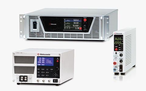
Matsusada Precision provides a diverse range of electronic load devices tailored for various applications. As the significance of DC power supplies continues to grow annually, electronic load equipment is becoming increasingly essential for verifying their performance.
High Power DC Electronic Load (EW Series)
This high-power electronic load device can handle up to 150 VDC and 480 A. With an optional booster (sold separately), you can connect up to five units in parallel, enabling a total load power of up to 12 kW. This capability establishes it as a truly high-power model.
Compact DC Electronic Load (EGS Series)
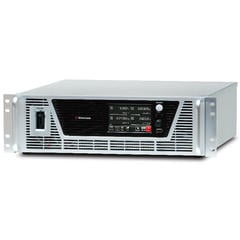
This compact DC electronic load device can handle up to 60 VDC and 10 A. Its lightweight design makes it easy to carry, making it ideal for field performance tests. This model is commonly used for performance verification of onboard instrumentation equipment.

Benchtop Type DC Electronic Load (EGD Series)
This tabletop model can handle up to 150 VDC and 60 A. It offers two control modes: constant current mode and constant resistance mode. The device is compatible with USB and LAN communication interfaces. Additionally, with an adapter (sold separately), five units can be installed in a 19-inch rack.

Multifunctional DC Electronic Load (EZD Series)
This model can handle up to 650 VDC and 50 A. It features seven control modes, including four basic modes and three composite modes. The device is designed for performance tests that require complex operations, such as pulse current discharge tests of rechargeable batteries and power supply load fluctuation tests.

Regenerative Electronic Load (PBR Series)
This model can handle up to 1500 VDC, 360 A, and 15 kW, with the option to expand by connecting multiple units together. It serves as a bidirectional power supply (regenerative power supply), capable of regenerating power from electronic loads. This device is ideal for testing batteries and bidirectional DC-DC converters. Additionally, the PBRM series, which integrates multiple PBR series units into a single cabinet, can manage even higher power levels.
