


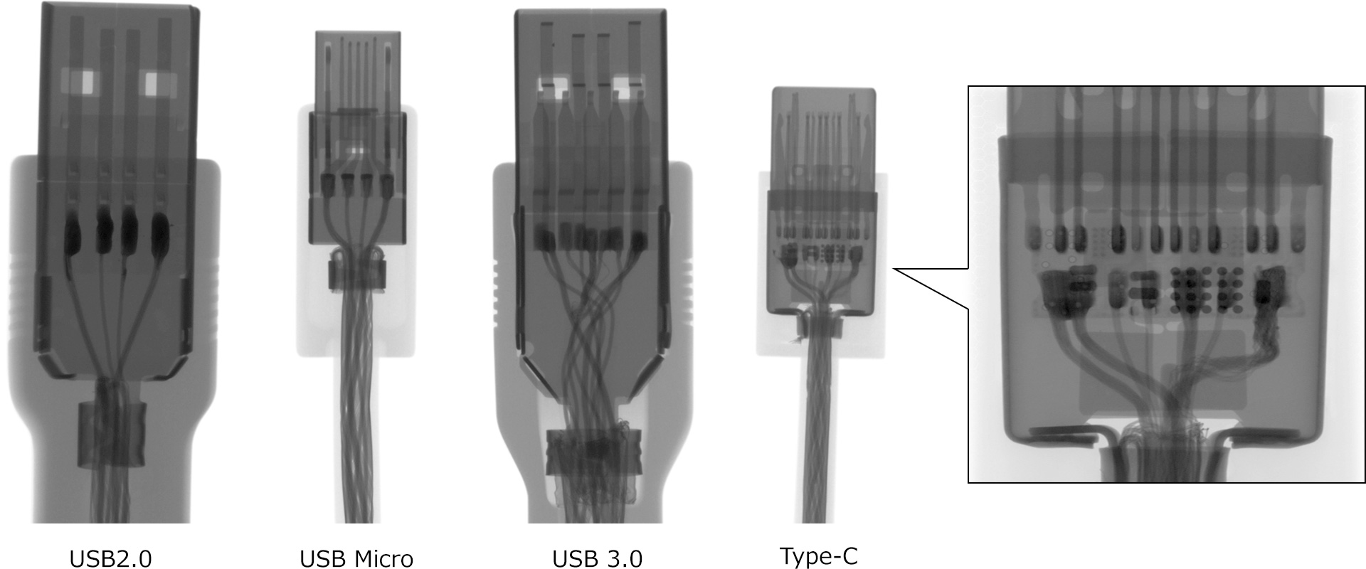
The X-ray images compare four different USB cables (from left to right): USB 2.0, USB Micro, USB 3.0, and Type-C cables. These represent the standard USB connector configurations: Type-A, Micro-B, Type-A, and Type-C, respectively. The X-ray examination reveals their internal structures, showing that USB 2.0 and Micro USB have four buses each, while USB 3.0 and Type-C feature six buses. The size comparison shows that Type-A has the largest, followed by Type-C, then Micro-B. A distinctive feature of the Type-C connector is the presence of an internal circuit board, which is clearly visible in the X-ray image.
X-ray system requirements
| Focal spot | Microfocus |
|---|---|
| X-ray tube voltage | 130 kV |
Recommended products

Information on related articles in Technical Knowledge
- The Right Way to Choose appropriate X-ray Inspection System
- Principles of Radiography
- How to use X-ray Inspection System safely
- What is Microfocus X-ray? (Basic Knowledge)
- Computed Tomography (CT) Basic and Principle
- Non-Destructive Testing: Types and Applications
- What are X-rays? (Basic Knowledge)
- How to Take a Computed Tomography? - X-Ray NDT series (1) -
- How to View X-ray CT Images - X-ray Non-Destructive Inspection series (2) -
- X-ray Image Processing and Automated Inspection - X-ray Non-Destructive Inspection series (3) -
- Types of X-ray tubes and high-voltage power supplies
- What is the difference between Radioactivity, Radiation, and Radioactive Materials?
- Radiation Effects on the Human body and the safety of X-ray equipment